
Machining high-density tungsten alloys tests even experienced shops. The material’s combination of extreme hardness and limited ductility creates conditions where cracks can appear without warning, turning what should be a straightforward turning or milling operation into an expensive lesson in material science. I’ve watched rejection rates climb past 15% on aerospace counterweight programs before the root cause became clear, and the fix almost always involves understanding what’s happening at the microstructural level before touching the machine controls.
Tungsten heavy alloys behave nothing like the steels or aluminum alloys most machinists cut daily. The microstructure tells the story: tungsten particles, typically comprising 85-97% of the material by weight, sit embedded in a nickel-iron or nickel-copper binder phase. That binder provides whatever ductility the material has, but with tungsten grains dominating the volume fraction, the composite inherits tungsten’s brittleness. When stress exceeds a threshold, the material fractures rather than yielding plastically.
Three mechanisms drive most cracking during machining. Thermal stress develops when the cutting zone heats rapidly from friction and deformation, then cools abruptly when coolant hits the surface. The temperature differential creates expansion and contraction gradients steep enough to exceed fracture strength in localized areas. Mechanical stress concentrations form at the tool-workpiece interface, particularly when worn tools or aggressive geometries force the material beyond its limits. Material imperfections, including porosity from incomplete sintering, inclusions, or weak grain boundaries, act as initiation sites where cracks nucleate under loads that intact material would survive.
On a counterweight program for an aerospace customer, we traced a 15% rejection rate to grain boundary weakness in the incoming material. The sintering process had left interfaces between tungsten grains and the binder phase that couldn’t withstand the combined thermal and mechanical loads of roughing passes. A revised pre-sintering treatment improved grain cohesion, and adjusting the machining sequence to reduce thermal gradients dropped cracking incidence below 2%. The machining parameters mattered, but the material condition determined whether those parameters would succeed.
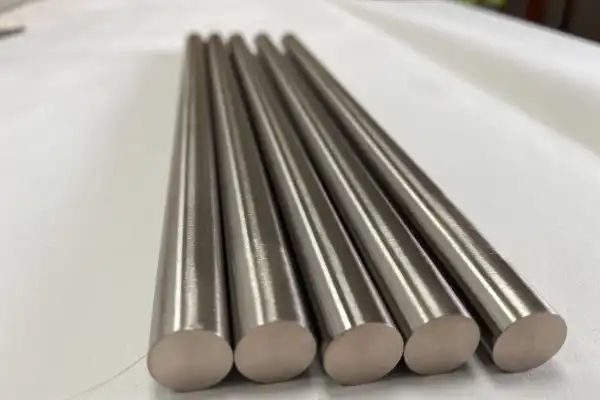
Every parameter choice either adds to or subtracts from the stress budget the material can tolerate before cracking. The table below summarizes the relationships, though the interactions between parameters often matter more than any single setting.
| Parameter | Impact on Cracking | Recommended Adjustment |
|---|---|---|
| Cutting Speed | Higher speeds generate more heat, increasing thermal stress and the risk of thermal shock when coolant contacts the heated zone. | Reduce cutting speed to limit heat generation. The productivity loss is real, but so is the scrap rate from running too fast. |
| Feed Rate | Excessive feed increases cutting forces and mechanical stress on the workpiece, particularly problematic when the tool encounters hard tungsten grains. | Use moderate to low feed rates to control chip load. The goal is consistent material removal without force spikes. |
| Depth of Cut | Large depths concentrate stress and heat in a smaller zone, overwhelming the material’s limited ability to dissipate energy. | Smaller depths of cut, especially for finishing passes, distribute stress over more passes and allow heat to conduct away between cuts. |
| Tool Geometry | Sharp tools with positive rake angles reduce cutting forces and heat generation. Negative rake or worn edges drag rather than cut, multiplying both thermal and mechanical loads. | Select tools with appropriate rake angles and edge preparations. Inspect edges frequently; what looks acceptable on steel may already be too worn for tungsten alloy. |
| Tool Material | Worn or inappropriate tool materials increase friction and heat while delivering inconsistent cutting action. | Carbide or ceramic tools with high wear resistance perform best. Replace tools before they show obvious wear; the damage to the workpiece happens before the tool looks bad. |
| Coolant Application | Inconsistent cooling creates thermal gradients that drive cracking. Intermittent coolant flow is worse than no coolant at all because it maximizes thermal shock. | Flood cooling with consistent flow, or minimum quantity lubrication systems designed for thermal management. The coolant must reach the cutting zone continuously. |
The machining operation inherits whatever stresses and defects exist in the incoming material. Addressing those conditions before the first cut prevents problems that no amount of parameter adjustment can fix afterward.
Stress relief annealing before machining reduces residual stresses from sintering or prior forming operations. The process involves heating to a temperature that allows the internal structure to relax, holding at temperature, then cooling slowly enough to avoid introducing new thermal stresses. For tungsten heavy alloys, the temperature and time must be controlled precisely to avoid changing the microstructure in ways that reduce density or mechanical properties. FOTMA provides guidance on thermal treatment parameters for specific alloy compositions.
Preheating the workpiece to 200-400°C before machining improves ductility during cutting and reduces the temperature differential between the cutting zone and bulk material. This approach works particularly well for large components or geometries with thin sections where thermal shock risk is highest. The practical challenge is maintaining uniform temperature throughout the cut, which may require heated fixtures or periodic reheating between passes.
Tooling quality determines whether the cutting action removes material cleanly or tears it. Fine-grained carbide with positive rake angles and adequate clearance reduces cutting forces and prevents chip re-cutting. Short tool overhangs minimize deflection and chatter, both of which introduce dynamic stresses that can initiate cracks. Rigid fixturing matters equally; any vibration translates directly into stress variations at the cutting zone.
A multi-pass strategy distributes the total material removal across more cuts, each generating less heat and force than a single aggressive pass. The additional machining time is offset by reduced scrap and rework. For critical components, the time spent on extra passes costs less than the time spent investigating why a part cracked.
Even optimized machining can leave residual stresses or surface conditions that affect long-term performance. Post-machining treatments and inspection close the loop on quality assurance.
A secondary stress relief anneal after machining addresses stresses introduced by the cutting process itself. Components with complex geometries or tight tolerances benefit most because machining-induced stresses can cause dimensional changes over time or reduce fatigue life. The treatment parameters depend on the alloy composition and the acceptable trade-offs between stress relief and any microstructural changes.
Surface finishing operations can either improve or degrade crack resistance depending on how they’re performed. Grinding must avoid generating enough heat to create surface burns or tensile residual stresses. Shot peening, when applicable, induces compressive residual stresses on the surface that inhibit crack initiation and slow propagation of any cracks that do form.
Non-destructive testing catches cracks that visual inspection misses. Ultrasonic testing detects subsurface flaws; dye penetrant inspection reveals surface-breaking cracks that might otherwise escape notice. For critical applications, FOTMA’s testing protocols include both methods to ensure components meet integrity requirements before shipment.
Microstructural analysis of sample sections confirms that machining has not introduced undesirable changes or micro-cracks invisible to NDT methods. This step is typically reserved for first-article qualification or periodic process verification rather than 100% inspection, but it provides the definitive answer about what the machining process is actually doing to the material.
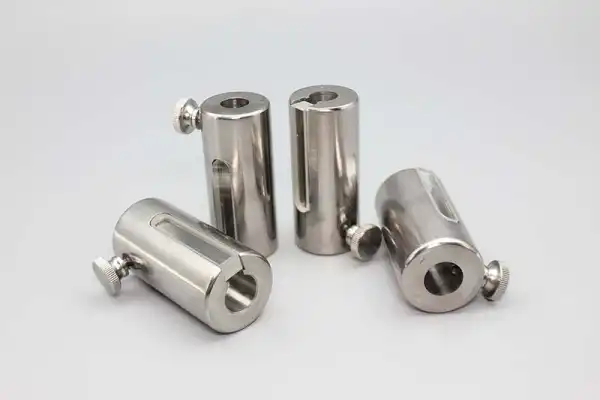
The choice of tungsten alloy composition affects machinability as much as any process parameter. Different binder systems and tungsten contents create materials with different ductility, toughness, and thermal properties.
Nickel-iron binders generally offer higher strength and ductility than nickel-copper binders, which translates to better tolerance for machining-induced stresses. Nickel-copper alloys are often specified for non-magnetic applications, but their lower ductility means tighter process windows during machining. Higher binder content increases ductility at the cost of density, so the material selection involves balancing the application requirements against machinability.
| Product Name | Key Characteristics | Typical Applications | Machinability Considerations |
|---|---|---|---|
| W-Ni-Fe (90-97% W) | High density, good strength, moderate ductility from iron-containing binder | Counterweights, radiation shielding, kinetic energy penetrators | Better machining tolerance than W-Ni-Cu; responds well to stress relief annealing |
| W-Ni-Cu (90-97% W) | High density, non-magnetic, lower ductility than W-Ni-Fe | Medical shielding, electrical contacts, non-magnetic balance weights | Requires more conservative parameters; higher cracking risk at equivalent settings |
| Lower tungsten content (85-90% W) | Reduced density, increased ductility, improved toughness | Applications where density can be traded for machinability | Easier to machine; wider parameter windows; lower cracking incidence |
FOTMA’s material specifications include machinability ratings based on production experience, which helps match alloy selection to manufacturing capability. If your shop has limited experience with tungsten alloys, starting with a more forgiving composition reduces the learning curve.
What cutting speed range minimizes cracking risk for tungsten heavy alloys?
Most shops find success between 30-60 surface meters per minute for turning operations, though the optimal speed depends on the specific alloy, tool material, and cooling setup. Starting at the low end of this range and increasing gradually while monitoring for thermal discoloration or micro-cracking provides a safer path than beginning with aggressive parameters. The speed that worked on the last tungsten job may not work on this one if the alloy composition or incoming material condition differs.
Can cracked tungsten alloy components be salvaged through welding or brazing?
Repair is rarely practical. The same brittleness that caused the original crack makes welded or brazed joints prone to cracking from thermal stresses during the joining process. Even if a joint survives fabrication, the heat-affected zone typically has degraded properties. For most applications, scrapping cracked components and addressing the root cause costs less than attempting repairs that may fail in service.
How does incoming material inspection prevent machining cracks?
Ultrasonic testing before machining detects porosity, inclusions, and other internal defects that would become crack initiation sites under machining loads. Rejecting defective material before it reaches the machine prevents wasted machining time and ensures that process optimization efforts address controllable variables rather than fighting material quality issues. The inspection cost is small compared to the cost of scrapping a partially machined component. To discuss inspection requirements or material specifications for your application, contact FOTMA’s technical team.
If you’re interested, check out these related articles:
Titanium And Titanium Alloys Widespread Application And Future Challenges
Panoramic Analysis Of Chinas Molybdenum Industry In 2025 Market Status And Downstream Application Discussion
What Is The Use Of Yg6 Carbide Tips
What Are The Properties Of Alsic Material
What Is A Titanium Rod Used For