Tungsten Alloy Sintering Porosity: Causes and Remedial Strategies
Tungsten alloy sintering porosity remains one of the more persistent headaches in powder metallurgy. These microscopic voids—often invisible until a part fails under load—can undermine mechanical strength, thermal conductivity, and long-term reliability in ways that surface inspection never catches. For engineers producing high-density tungsten components, understanding how pores form and when to intervene makes the difference between consistent output and costly scrap rates. How Porosity Forms During Tungsten Alloy Sintering Porosity in sintered tungsten alloys originates at multiple stages of the powder metallurgy process, and each stage offers different intervention points. Sintering bonds powder particles through heat and pressure without full liquefaction, densifying the material as particles fuse. The voids that remain fall into two categories: open porosity, where channels connect to the surface, and closed porosity, where isolated pockets trap gas within the structure. Both reduce the effective load-bearing cross-section. Scanning electron microscopy reveals not just the presence of pores but their distribution and shape, information that points back to specific process failures. The green compact density—the density of pressed powder before sintering—sets the upper limit on final density. A green compact with uneven density or low overall compaction carries those defects through the entire thermal cycle. Porosity Type Characteristics Impact on Performance Open Porosity Interconnected channels Allows fluid penetration, reduces strength Closed Porosity Isolated voids Traps gases, reduces thermal conductivity Intergranular Along grain boundaries Weakens grain cohesion, promotes fracture Intragranular Within grains Less common, still detrimental to strength Where Porosity Originates in the Sintering Process Defects can emerge from powder characteristics, compaction parameters, or atmosphere control during sintering. Powder quality matters more than many operators realize. Inconsistent particle size distribution, irregular particle shapes, or surface oxides lead to non-uniform packing during compaction. Those initial voids persist through sintering. Compaction pressure and its distribution across the die cavity determine green density uniformity. Insufficient pressure leaves loose regions; uneven pressure creates density gradients that cause differential shrinkage. Binder removal, the step where organic additives burn off, requires careful thermal management. Heating too fast traps volatiles inside the compact, and those trapped gases nucleate pores or cause cracking. The sintering atmosphere, typically hydrogen for tungsten, prevents oxidation and promotes densification. Temperature uniformity across the furnace matters equally. Hot spots accelerate local densification while cold spots lag behind, creating internal stress and pore networks. Excessive grain growth at high temperatures compounds the problem, as large grains leave voids at boundaries where smaller
Designing Custom Tungsten Dart Barrels for European Brands
The European dart market demands precision and performance, leading many brands to seek specialized manufacturing partners. Crafting custom tungsten dart barrels requires a deep understanding of material science and advanced engineering. This article explores how we collaborate with European brands to deliver high-quality, bespoke dart components that meet stringent performance and aesthetic requirements. Our expertise in high-density alloys and precision machining ensures superior products for competitive play. What a European Brand Needed from Their Dart Barrel Supplier A prominent European sports equipment brand came to us with a clear objective: create a new line of darts that would redefine performance and stand out in a competitive market. They wanted superior material characteristics and unparalleled precision in their custom dart design, which meant finding a partner with extensive expertise in high-density alloys and specialized manufacturing capabilities. The client’s specifications were rigorous. They focused on exact weight distribution, specific grip patterns, and a durable surface finish to optimize dart performance. This presented an opportunity to apply our knowledge in non-ferrous metals to a demanding application where tolerances matter and shortcuts show up immediately in player feedback. Why Tungsten Alloys Dominate Competitive Dart Barrel Design Tungsten alloys are the material of choice for high-performance dart barrels due to their exceptional properties. The high density of tungsten allows for a smaller barrel diameter at a given weight, which improves grouping and reduces air resistance. This characteristic is critical for competitive players seeking consistent flight paths and tighter spreads. Tungsten-nickel-iron alloys combine tungsten’s density with the ductility and machinability of nickel and iron, creating a material that is both heavy and workable. We often work with high-density tungsten alloys, specifically Tungsten Heavy Alloy (WHA), which typically contains 85–97% tungsten with nickel and iron or copper as binders. These alloys are produced through powder metallurgy techniques. The process involves pressing tungsten powder with binder elements into a desired shape, then sintering it at high temperatures to achieve a dense, homogeneous structure. The resulting material is not only dense but also strong, tough, and corrosion-resistant, making it ideal for the demanding application of dart barrels. Material Type Density (g/cm³) Hardness (HV) Key Benefit for Darts Tungsten Heavy Alloy 17.0–18.5 280–350 High density, small diameter Brass 8.4–8.7 80–120 Economical, larger diameter Nickel Silver 8.5–8.8 100–150 Good balance, moderate density Tungsten’s high density (approximately 19.3 grams per cubic centimeter for pure tungsten) allows manufacturers to produce slender dart barrels
Tungsten Shields: Replacing Lead for Optimal Radiation Safety
For decades, lead served as the default radiation shielding material across medical, nuclear, and industrial applications. That default is shifting. Tungsten’s density advantage—up to 19.3 g/cm³ versus lead’s 11.34 g/cm³—delivers equivalent attenuation in thinner profiles, while eliminating the toxicity concerns that now drive regulatory pressure worldwide. The transition represents more than compliance; it changes how shielding systems are designed, fabricated, and maintained over their operational life. Why Lead Replacement Has Become Unavoidable Lead’s practical advantages—high density, low cost, easy machining—made it the obvious choice for radiation shielding throughout the twentieth century. Those advantages no longer outweigh the liabilities. Regulatory frameworks have tightened considerably. The EU’s RoHS directive restricts lead in electronic equipment. OSHA’s permissible exposure limits for airborne lead have dropped repeatedly since the 1970s. Medical device manufacturers face increasing scrutiny over lead content in equipment that contacts patients or operators. These aren’t theoretical concerns—they translate directly into compliance costs, specialized handling requirements, and hazardous waste disposal fees that accumulate over a shielding system’s lifetime. The health risks are well-documented. Lead exposure affects neurological function, kidney performance, and reproductive health. Workers fabricating or installing lead shields require respiratory protection, blood lead monitoring, and decontamination procedures. Environmental persistence compounds the problem: lead contamination in soil and groundwater can remain for centuries, creating long-term liability exposure for facility operators. For procurement teams evaluating total cost of ownership, these factors shift the calculation. The question is no longer whether to transition away from lead, but how to do so without sacrificing shielding performance. How Tungsten’s Physical Properties Enable Better Shielding Design Radiation attenuation depends on material density and atomic number. More atoms per unit volume means more opportunities for incoming radiation to interact with the shielding material. Tungsten’s density advantage is substantial—approximately 70% higher than lead at comparable alloy compositions. This density difference has direct design implications. A tungsten shield can achieve the same attenuation as a lead shield while occupying significantly less volume. In applications where space is constrained—medical imaging gantries, portable radiography equipment, aerospace systems—this translates to smaller device footprints and reduced weight. The mechanical properties differ as well: tungsten alloys maintain structural integrity under conditions that would deform lead, and their corrosion resistance eliminates degradation concerns in humid or chemically active environments. Feature Tungsten Heavy Alloy (WHA) Lead (Pb) Density 17.0 – 19.3 g/cm³ 11.34 g/cm³ Toxicity Non-toxic Highly toxic Melting Point ~3422 °C (pure W) 327.5 °C Mechanical Strength
Tungsten TIG Electrode Contamination: Troubleshooting and Solutions
Achieving high-quality welds in Gas Tungsten Arc Welding relies heavily on the integrity of the tungsten electrode. Contamination of this critical component leads to immediate and severe degradation of weld quality, causing arc instability, poor penetration, and costly rework. Understanding the signs, causes, and solutions for tungsten TIG electrode contamination is essential for any welding professional seeking consistent, reliable results. How to Identify Tungsten TIG Electrode Contamination Early detection prevents costly rework and ensures consistent weld quality. A clean electrode tip maintains a stable, focused arc, producing a smooth and consistent weld bead. A contaminated electrode will exhibit distinct visual cues and negatively impact welding performance. Even slight discoloration or pitting on the electrode tip can dramatically alter arc behavior. Characteristic Clean Electrode Tip Contaminated Electrode Tip Appearance Smooth, shiny, pointed or balled (AC welding) Dull, blackened, pitted, lumpy, or with foreign material Arc Stability Consistent, focused, quiet Erratic, wandering, sputtering, noisy Weld Bead Quality Smooth, uniform, good penetration, minimal spatter Rough, inconsistent, poor penetration, porosity, inclusions Electrode Consumption Slow, predictable Rapid, excessive burn-off, premature degradation When the arc becomes erratic or the weld bead shows signs of porosity or tungsten inclusions, the electrode tip is often the culprit. These inclusions, small pieces of tungsten embedded in the weld metal, severely compromise the mechanical properties of the joint. Visual inspection before each weld pass can save significant time and material by preventing these defects. What Causes TIG Electrode Contamination Understanding the precise causes of contamination is fundamental to implementing effective prevention strategies. Tungsten TIG electrode contamination can stem from various sources, often a combination of factors related to materials, equipment, and technique. Identifying the root cause allows for targeted solutions rather than simply regrinding and repeating the problem. Tungsten electrode contamination typically arises from contact with the workpiece, filler metal, or atmospheric impurities during welding. Poor shielding gas coverage, incorrect welding parameters, and improper electrode preparation are also significant contributors. On one project involving the welding of thin-gauge stainless steel, persistent porosity was traced back to a batch of filler wire with microscopic surface oxides. This seemingly minor impurity led to repeated tungsten contamination and a 30% increase in rework, underscoring the critical importance of material purity across all welding consumables. Common causes include: Workpiece Contact: Touching the electrode to the molten weld puddle or the base metal. Filler Metal Contact: Accidentally dipping the hot electrode into the filler rod.
Carbide Tool Chipping: Preventing Failures for Precision
Carbide tool chipping costs more than the replacement insert. When a cutting edge fractures mid-cycle, the immediate loss is the tool itself. The secondary losses—scrapped parts, interrupted production, surface finish rework, and the time spent diagnosing what went wrong—often exceed the tool cost by a factor of five or more. The problem compounds in high-volume operations where a single chipped insert can propagate defects across dozens of parts before anyone catches it. The frustrating part is that most chipping is preventable. The fractures follow predictable patterns tied to specific combinations of cutting parameters, material properties, and tool geometry. Once you understand what drives the failure mode, the fixes are usually straightforward adjustments rather than expensive overhauls. Why Carbide Edges Fracture in the First Place Carbide tool chipping happens when localized stress at the cutting edge exceeds the material’s fracture toughness. The stress can be mechanical, thermal, or both acting together. What makes carbide tricky is that it combines extreme hardness with relatively low ductility—the same property that lets it hold a sharp edge also makes it brittle under the wrong conditions. Micro-chipping shows up as hairline fractures along the cutting edge, often invisible without magnification. These small fractures accumulate over time, gradually dulling the edge and increasing cutting forces. The progression is slow enough that operators sometimes attribute the degraded performance to normal wear rather than recognizing the underlying chipping mechanism. Macro-chipping is harder to miss. A visible chunk of the cutting edge breaks away, sometimes taking enough material to render the insert unusable in a single event. The causes differ from micro-chipping: sudden impact loads, severe thermal gradients, or material defects within the carbide substrate itself. Characteristic Micro-Chipping Macro-Chipping Size of Fracture Microscopic, hairline cracks Visible, larger fragments Primary Cause Abrasive wear, thermal fatigue High impact loads, severe thermal shock Progression Gradual, leads to edge dulling Sudden, catastrophic tool failure Impact on Workpiece Poor surface finish, dimensional drift Severe surface damage, scrap parts Detection Microscopic inspection, process monitoring Visual inspection during or after cut The distinction matters for troubleshooting. Micro-chipping points toward cumulative stress factors like thermal cycling or abrasive wear. Macro-chipping usually indicates a discrete event: an interrupted cut, a hard inclusion in the workpiece, or a parameter setting that pushed the tool past its mechanical limits. How Cutting Parameters Create the Conditions for Failure The relationship between machining parameters and carbide tool chipping is direct but not
Tungsten Alloy Cracking During Machining: Causes and Prevention
Machining high-density tungsten alloys tests even experienced shops. The material’s combination of extreme hardness and limited ductility creates conditions where cracks can appear without warning, turning what should be a straightforward turning or milling operation into an expensive lesson in material science. I’ve watched rejection rates climb past 15% on aerospace counterweight programs before the root cause became clear, and the fix almost always involves understanding what’s happening at the microstructural level before touching the machine controls. Why Tungsten Alloys Crack Where Other Metals Deform Tungsten heavy alloys behave nothing like the steels or aluminum alloys most machinists cut daily. The microstructure tells the story: tungsten particles, typically comprising 85-97% of the material by weight, sit embedded in a nickel-iron or nickel-copper binder phase. That binder provides whatever ductility the material has, but with tungsten grains dominating the volume fraction, the composite inherits tungsten’s brittleness. When stress exceeds a threshold, the material fractures rather than yielding plastically. Three mechanisms drive most cracking during machining. Thermal stress develops when the cutting zone heats rapidly from friction and deformation, then cools abruptly when coolant hits the surface. The temperature differential creates expansion and contraction gradients steep enough to exceed fracture strength in localized areas. Mechanical stress concentrations form at the tool-workpiece interface, particularly when worn tools or aggressive geometries force the material beyond its limits. Material imperfections, including porosity from incomplete sintering, inclusions, or weak grain boundaries, act as initiation sites where cracks nucleate under loads that intact material would survive. On a counterweight program for an aerospace customer, we traced a 15% rejection rate to grain boundary weakness in the incoming material. The sintering process had left interfaces between tungsten grains and the binder phase that couldn’t withstand the combined thermal and mechanical loads of roughing passes. A revised pre-sintering treatment improved grain cohesion, and adjusting the machining sequence to reduce thermal gradients dropped cracking incidence below 2%. The machining parameters mattered, but the material condition determined whether those parameters would succeed. How Machining Parameters Shift the Cracking Threshold Every parameter choice either adds to or subtracts from the stress budget the material can tolerate before cracking. The table below summarizes the relationships, though the interactions between parameters often matter more than any single setting. Parameter Impact on Cracking Recommended Adjustment Cutting Speed Higher speeds generate more heat, increasing thermal stress and the risk of thermal shock when coolant contacts the
Tungsten Rarity: Supply Chain Dynamics and China’s Global Role
Tungsten sits at the center of a supply chain problem that most procurement teams underestimate until they face it directly. The metal’s combination of extreme hardness, the highest melting point of any element, and density makes it irreplaceable in applications from cutting tools to aerospace components. What makes sourcing complicated is not just geological scarcity but the concentration of production capacity in a single country. China controls roughly 80% of global tungsten concentrate output, a dominance that extends through refining and processing. For strategic planners managing material security, this concentration creates exposure that standard diversification playbooks struggle to address. Why Tungsten Supply Concentration Creates Real Procurement Risk Tungsten occurs primarily in wolframite and scheelite deposits, minerals that require energy-intensive extraction and processing. The geological distribution is uneven, with economically viable deposits concentrated in a handful of regions. This natural scarcity combines with processing complexity to create a market where supply disruptions translate quickly into price volatility and allocation challenges. Global Tungsten Reserves by Country (Estimated) Country Estimated Reserves (Metric Tons) China 1,900,000 Russia 400,000 Vietnam 95,000 Canada 87,000 United States 69,000 Bolivia 52,000 The reserve figures tell only part of the story. Production capacity, processing infrastructure, and export policy determine actual availability far more than raw reserve numbers. A country might hold significant reserves while lacking the refining capability to deliver material that meets industrial specifications. What applications drive tungsten demand and why substitution remains difficult Tungsten’s demand profile reflects its unique property combination. Cemented carbides for cutting tools, drills, and wear-resistant components account for the largest share of consumption. The material’s hardness at elevated temperatures makes it essential for machining operations where other materials would fail. Filament applications in specialty lighting, electrodes for welding and electrical discharge machining, and high-temperature alloys for turbine components represent additional demand centers. Radiation shielding applications leverage tungsten’s density, which exceeds lead while avoiding toxicity concerns. Each application exploits a specific property combination that alternative materials cannot fully replicate. How China’s Market Position Affects Global Tungsten Availability China’s dominance in tungsten extends beyond mining into the processing stages where raw concentrate becomes usable industrial material. This vertical integration means that even tungsten mined elsewhere often flows through Chinese processing facilities before reaching end users. The practical effect is that supply chain disruptions in China ripple through global markets regardless of where the original ore was extracted. Export regulations, production quotas, and environmental enforcement actions
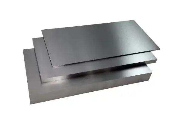
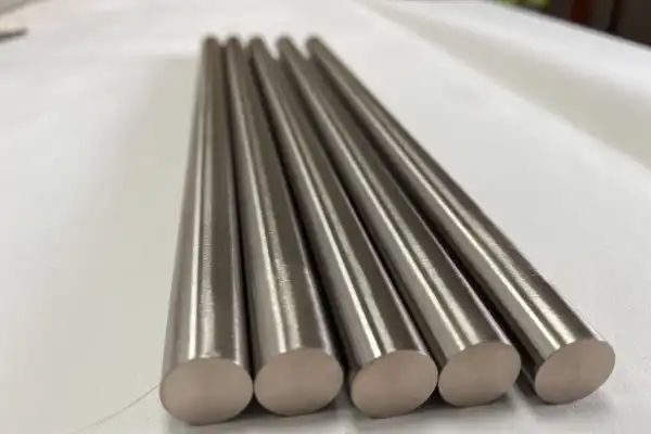
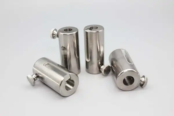
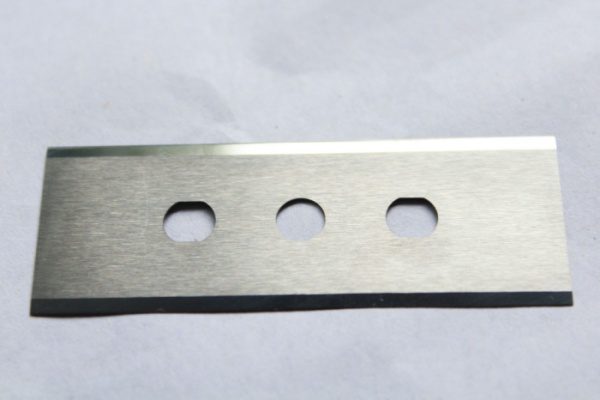
FOTMA’s Product Range: Specialized Metal Materials for Industry
High-Performance Tungsten and Molybdenum Materials for Industrial Applications Tungsten and molybdenum sit at the foundation of high-temperature industrial processing. These refractory metals handle conditions that would destroy conventional steels or aluminum alloys, which is why they appear in vacuum furnaces, aerospace thermal structures, and power electronics where failure is not an option. At Hubei Fotma Machinery Co., Ltd., we produce these materials in forms ranging from pure plates and wires to engineered composites that balance thermal expansion, conductivity, and mechanical strength for specific operating environments. The practical value of tungsten comes from its 3422°C melting point and extreme hardness. Molybdenum, while slightly lower at 2620°C, offers better machinability and thermal conductivity that makes it preferable for heat sink applications. Neither material works in isolation for most modern applications, so we engineer alloys and composites that combine their strengths with copper, nickel, or iron binders depending on what the end use demands. Why Tungsten-Molybdenum Alloys Outperform Single-Metal Solutions Pure tungsten and pure molybdenum each have limitations that become apparent in real operating conditions. Tungsten’s brittleness at room temperature makes machining difficult and creates fracture risks during thermal cycling. Molybdenum oxidizes rapidly above 500°C in air, restricting its use to vacuum or inert atmospheres unless protected. Alloys and composites solve these problems by introducing complementary properties. Our Molybdenum-Copper (MoCu) Alloy demonstrates this principle. The powder-metallurgy process allows us to adjust the Mo/Cu ratio to match specific coefficient of thermal expansion (CTE) requirements, typically targeting 6-8 ppm/°C for semiconductor packaging applications. The copper phase provides thermal conductivity exceeding 160 W/m·K while the molybdenum skeleton maintains structural rigidity at temperatures that would soften pure copper. This combination makes MoCu the standard choice for high-power IGBT base plates and RF module heat spreaders. Tungsten-Copper (W-Cu) alloys follow similar logic but target applications requiring higher density and arc resistance. The tungsten phase resists erosion from electrical arcing, which is why W-Cu appears in high-voltage switchgear contacts and resistance welding electrodes. We typically produce these at 70-90% tungsten content, adjusting the ratio based on whether the application prioritizes arc resistance or thermal management. Material Specifications That Matter for Thermal Management Applications Electronic packaging engineers spend considerable time matching CTE between substrates, die attach materials, and heat sinks. A mismatch of even 2-3 ppm/°C creates thermal stress during power cycling that eventually causes solder joint fatigue or die cracking. Our CMC (Copper-Molybdenum-Copper) composite addresses this by sandwiching a
Molybdenum Uses: Key Industrial Applications and Properties
Molybdenum sits in a category of metals that engineers reach for when nothing else survives the operating environment. Its melting point of 2620°C places it among the highest of any element—only tungsten, rhenium, and tantalum exceed it. That thermal stability, combined with strength retention at temperatures above 1900°C and resistance to corrosion from acids and molten metals, explains why molybdenum appears in applications ranging from aerospace heat shields to chemical processing equipment. The material’s behavior under extreme conditions makes it worth understanding in detail, particularly for anyone specifying components that will see sustained high temperatures or aggressive chemical exposure. What Gives Molybdenum Its Performance Characteristics The atomic structure of molybdenum produces a set of properties that work together in high-temperature service. The metal maintains mechanical integrity at temperatures where most alternatives have already softened or failed entirely. Thermal conductivity is high enough to move heat efficiently through components, which matters in applications like furnace elements or heat sinks where thermal management determines component life. Electrical conductivity is sufficient for use in electrical contacts and interconnects. The coefficient of thermal expansion stays low relative to most metals, reducing the dimensional changes that cause stress failures in assemblies subjected to temperature cycling. These characteristics combine to produce a material that holds its shape and strength in environments that destroy conventional engineering metals. The modulus of elasticity is high, meaning the metal resists deformation under load. The strength-to-weight ratio is favorable enough that structural applications remain practical without excessive mass penalties. Corrosion resistance extends to many acids and to contact with molten metals, which opens applications in chemical processing and metallurgical equipment. The resistance is not universal—oxidation becomes significant above certain temperatures in air—but the envelope of protection is broad enough to cover many demanding service conditions. How Alloying Extends the Performance Envelope Pure molybdenum already offers impressive properties, but alloying pushes the performance boundaries further for specific applications. The additions are typically small in percentage terms but produce measurable improvements in targeted characteristics. TZM alloy contains titanium and zirconium additions that increase high-temperature strength and creep resistance compared to unalloyed molybdenum. The improvement shows up in applications where components must resist deformation under sustained stress at elevated temperatures—furnace structural elements, for example, or tooling that sees repeated thermal cycling. Molybdenum-rhenium alloys trade some of the base metal’s characteristics for improved ductility and weldability. The rhenium addition makes fabrication of complex shapes more