Sourcing Copper-Nickel Alloys from China: Forms and Quality
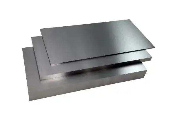
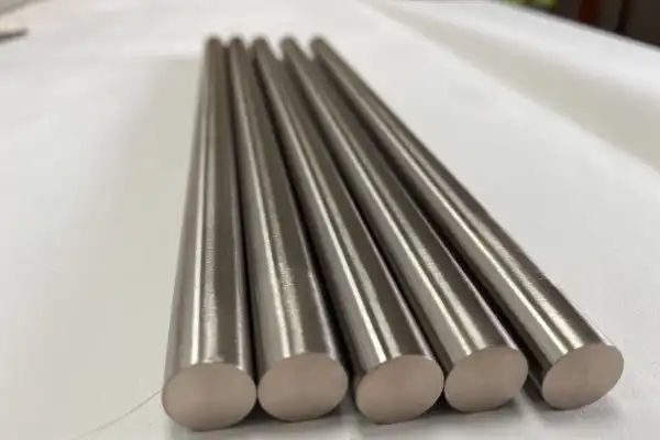
Procuring copper-nickel alloys from international markets requires attention to both material specifications and supplier reliability. These alloys deliver properties that matter in demanding applications, so quality cannot be an afterthought. Understanding the available forms and the quality control processes behind them is fundamental for successful global sourcing. A strategic approach to selecting Chinese suppliers can yield real advantages in cost and material availability. What Makes Copper-Nickel Alloys Worth the Specification Effort Copper-nickel alloys, commonly abbreviated as CuNi, are copper-based materials with nickel as the primary alloying element. They earn their reputation through exceptional corrosion resistance, particularly in marine and industrial environments where other materials fail within years. Nickel additions strengthen copper and reduce biofouling, the accumulation of microorganisms, plants, and algae that degrades performance over time. Different grades serve different conditions: CuNi 90/10 (90% copper, 10% nickel) handles moderate seawater exposure, while CuNi 70/30 (70% copper, 30% nickel) performs in more aggressive environments where chloride concentrations run higher. Beyond corrosion resistance, CuNi alloys offer good thermal conductivity, moderate electrical conductivity, and excellent ductility for fabrication. These combined properties make them difficult to replace in industries from shipbuilding to power generation. Desalination plants specify CuNi alloys for heat exchanger tubes because the material withstands aggressive seawater conditions that would pit stainless steel within months. Offshore oil and gas platforms rely on them for piping systems and risers where both corrosion and erosion act simultaneously. FOTMA’s expertise in non-ferrous metals supports custom alloy solutions, helping clients select the optimal CuNi grade for their specific operating conditions. How Sheet, Tube, Pipe, and Wire Specifications Differ in Practice The form of copper-nickel alloy, whether sheet, tube, pipe, or wire, follows from the intended application, and each form carries its own specification requirements and fabrication considerations. Copper-nickel sheets serve cladding, heat exchanger plates, and structural components in marine vessels where surface protection matters. Tubes and pipes handle heat exchangers, condensers, and fluid transport systems, especially where corrosive fluids like seawater flow continuously. Wire forms appear in electrical components, fasteners, and welding electrodes. Each form must meet specific industry standards. ASTM B111 governs seamless CuNi condenser tubes, while ASTM B151 covers CuNi rods, bars, and shapes. These standards define chemical composition, mechanical properties, dimensions, and testing requirements. When sourcing, specifying these standards clearly prevents material compatibility problems downstream. Working with clients to refine specifications ensures that the chosen form and grade align with project demands before
Copper-Nickel Alloy: Essential Properties, Grades, and Uses
Copper-nickel alloy is a copper-based material where nickel serves as the main alloying addition, delivering strong corrosion resistance and solid mechanical performance. These alloys handle harsh service conditions where other metals fail prematurely. Engineers and procurement teams working with marine systems, heat exchangers, or offshore equipment need to understand how different grades perform and where each fits best. What Makes Copper-Nickel Alloys Work Copper-nickel alloys form a solid solution where nickel content typically runs from 1.5% to 45%. This structure changes copper’s baseline properties in useful ways. Adding nickel raises strength and ductility while dramatically improving corrosion resistance, particularly in seawater and brackish environments. Small amounts of iron and manganese refine the alloy further. Iron increases resistance to impingement corrosion, the localized attack that happens when fluid hits a surface at high velocity. Manganese works as a deoxidizer during melting, cleaning up the metal before it solidifies. The corrosion resistance comes from a protective film that forms on the surface when the alloy contacts seawater or other corrosive media. This film, built from copper and nickel oxides, repairs itself when damaged and blocks further attack. The film takes time to mature, usually reaching full effectiveness after several weeks of exposure. Once established, it provides decades of protection. Biofouling resistance sets copper-nickel apart from stainless steel and carbon steel alternatives. Marine organisms like barnacles and algae struggle to attach and grow on these surfaces. In heat exchangers, this keeps tubes clean and maintains thermal efficiency without constant cleaning. On ship hulls, it reduces drag and fuel consumption. I have seen heat exchangers made from copper-nickel run for years with minimal fouling while adjacent stainless steel units required quarterly cleaning to maintain performance. How Copper-Nickel Compares to Alternative Materials The property combination in copper-nickel alloys creates advantages that single-property materials cannot match. Tensile strength ranges from 300 to 500 MPa depending on grade and temper, with good ductility that allows forming and bending without cracking. Thermal conductivity sits between 29 and 40 W/mK, lower than pure copper but adequate for heat transfer applications. Electrical conductivity decreases as nickel content rises, though it remains acceptable for many electrical components. Seawater corrosion resistance is where copper-nickel alloys excel. They resist general corrosion, pitting, and crevice corrosion, failure modes that plague carbon steel and even some stainless grades in marine service. Stress corrosion cracking, where tensile stress and corrosive environment combine to cause sudden brittle
Molybdenum Electrode Degradation in Glass Furnaces: Causes & Remedies
Molybdenum electrodes deliver the Joule heating that keeps glass melting furnaces at operating temperature, yet they sit in one of the most punishing environments in industrial processing. Molten glass attacks them chemically, the atmosphere above the melt oxidizes exposed surfaces, and the electrical current passing through them accelerates corrosion at the interface. When an electrode fails, the furnace goes cold and production stops until the damage is repaired. Understanding why these electrodes wear—and what can be done about it—directly affects campaign length, maintenance budgets, and glass quality consistency. How Molybdenum Electrodes Actually Degrade in Service Three mechanisms account for most electrode material loss, and they often operate simultaneously. Chemical attack occurs when alkali oxides and multivalent ions in the glass react with the molybdenum surface. The reaction products dissolve into the melt, carrying electrode material away and gradually reducing the cross-section. Glasses with higher soda or potash content tend to be more aggressive, and the rate increases with temperature. Oxidation becomes a problem wherever the electrode is exposed to oxygen—typically at the glass line or above it. Molybdenum forms volatile oxides at furnace temperatures, and these oxides evaporate rather than building up as a protective layer. If the glass level drops or fluctuates, fresh electrode surface is repeatedly exposed to the furnace atmosphere, and thinning accelerates. I have seen electrodes lose measurable diameter within weeks when level control was inconsistent. Electrochemical corrosion is driven by the current itself. The molten glass acts as an electrolyte, and the passage of current can either accelerate dissolution or create resistive surface layers that cause localized overheating. Current density variations show up as bright spots on the electrode surface during operation—visible indicators that one section is working harder than the rest. In one case, redistributing power across multiple electrodes reduced the average degradation rate by roughly 15 percent over six months and pushed the maintenance window out accordingly. These mechanisms interact. High temperature speeds chemical reactions. Uneven current distribution creates hot spots that accelerate both oxidation and corrosion. The viscosity of the melt limits diffusion, so protective layers cannot form, and fresh electrode material stays exposed to corrosive agents. What Operational Factors Actually Control Electrode Wear The degradation mechanisms are inherent to the system, but the rate at which they proceed depends heavily on how the furnace is operated. Glass composition is the starting point. Higher alkali content and certain heavy metal oxides make
Tungsten Crankshaft Weights: Boosting Motorsport Engine Performance
Getting serious power from a motorsport engine means obsessing over rotational dynamics. The crankshaft sits at the center of that obsession—it converts piston motion into rotational force, and any imbalance there costs you power, durability, and throttle response. Tungsten crankshaft weights solve problems that conventional materials cannot, particularly when you need precise mass placement in tight spaces while keeping rotating inertia low. For OEMs pushing engine designs toward higher RPM limits, this material choice has become a baseline requirement rather than an exotic option. Why Crankshaft Balance Determines Your RPM Ceiling Crankshaft balancing is not a finishing touch. It is a structural requirement that sets the upper boundary of your engine’s operating range. At the RPMs common in motorsport (often exceeding 10,000), even small imbalances create vibration amplitudes that accelerate bearing wear, reduce mechanical efficiency, and force conservative rev limits. The counterweights on a crankshaft exist to cancel the inertial forces from reciprocating pistons and connecting rods. When those forces are not fully canceled, the engine shakes itself apart. The relationship between balance quality and usable power is direct. A well-balanced crankshaft loses less energy to vibration, which means more of your combustion pressure reaches the drivetrain. Throttle response improves because the rotating assembly resists RPM changes less aggressively. Dynamic balancing (achieving equilibrium across the full RPM range, not just at rest) requires placing mass precisely where the physics demand it. In a racing engine, where packaging constraints are severe and every gram matters, the ability to achieve that balance in a compact envelope determines what the engine can actually do on track. What Makes Motorsport Crankshaft Material Selection Difficult Selecting materials for motorsport crankshafts involves trade-offs that do not exist in standard automotive applications. OEMs need components that are simultaneously lighter, stronger, and more durable than previous generations, often while fitting into tighter packaging. The material for counterweights specifically must satisfy several competing requirements. Fatigue resistance tops the list. A crankshaft endures millions of stress cycles at elevated temperatures. The material must tolerate this loading without crack initiation or propagation. Thermal stability matters because crankshafts operate in environments where temperatures fluctuate significantly during a race. Materials that soften, expand unpredictably, or lose stiffness at operating temperatures create balance problems that worsen as the engine heats up. Durability under shock loading, exposure to oil contaminants, and occasional debris ingestion is non-negotiable. The strength-to-weight ratio requirement creates the central tension. Reducing
Why Carbide Wear Parts Fail Early: Understanding 5 Core Causes
Carbide wear parts keep production running in mining, metalworking, oil and gas, and dozens of other sectors where abrasion, impact, and heat would destroy softer materials within hours. When these components fail ahead of schedule, the costs go beyond replacement parts. Downtime stacks up, maintenance crews scramble, and budgets built around predictable wear cycles fall apart. Most premature failures trace back to five root causes, and each one is preventable once you know what to look for. This article breaks down those five causes and explains how to address them before they shut down your line. Why Carbide Wear Parts Matter More Than Most Operators Realize Cemented carbide, usually tungsten carbide particles held together by a cobalt binder, earns its place in cutting tools, dies, nozzles, and protective linings because nothing else survives the same punishment at the same cost. The material holds a sharp edge under continuous abrasive contact, resists deformation at elevated temperatures, and tolerates corrosive environments that would pit or dissolve tool steels. When a carbide component fails early, the ripple effect hits production schedules, spare parts inventory, and total cost of ownership. A single unplanned replacement can cost ten times what the part itself costs once you factor in labor, lost output, and expedited shipping. How Material Composition and Quality Defects Lead to Early Failure The performance ceiling of any carbide part is set at the powder stage. Tungsten carbide grains are sintered with a metallic binder, and the ratio between them determines whether the finished part favors hardness or toughness. Smaller grains pack more boundaries into the same volume, raising hardness and abrasive wear resistance. Higher binder content absorbs impact energy better but softens the matrix slightly. Problems start when the grain size distribution is inconsistent, when impurities contaminate the powder, or when voids form during sintering. Each of these defects creates a stress concentrator, a point where cracks initiate under load that would otherwise be routine. Not all cemented carbides resist wear equally. A grade optimized for continuous sliding abrasion will chip under repeated impact because it lacks the toughness to absorb shock. A grade designed for impact will wear too fast in a high-velocity slurry because its binder content sacrifices hardness. Matching the grade to the application is the first line of defense against premature failure. Where Design Flaws and Manufacturing Imperfections Create Weak Points Correct material selection means nothing if the part
WCu Heat Sinks: Elevating 5G Base Station Antenna Performance
5G base stations run hot. The combination of higher frequencies, denser component packing, and continuous operation pushes thermal limits that older network generations never approached. When a power amplifier in an active antenna unit overheats, the consequences cascade: signal quality drops, data rates fall, and in severe cases, the hardware fails outright. WCu heat sinks address this problem directly. The tungsten-copper composite pulls heat away from GaN devices and RF modules faster than most alternatives, while its thermal expansion behavior matches the semiconductors it protects. That match matters because repeated heating and cooling cycles will crack a heat sink that expands at a different rate than the chip it contacts. Why 5G Thermal Loads Exceed Previous Network Generations Fifth-generation wireless technology packs more processing power into smaller enclosures than any prior standard. Active antenna units integrate power amplifiers, digital signal processors, and beamforming electronics into a single housing. Each component generates heat. When they share a confined space, that heat accumulates faster than passive airflow can remove it. The physics are straightforward. Higher frequencies require more power to maintain signal strength over distance. More power means more waste heat. A 5G base station operating at 3.5 GHz or higher frequencies dissipates substantially more thermal energy than a 4G equivalent serving the same coverage area. If that heat stays trapped near the semiconductors, junction temperatures rise. Elevated junction temperatures degrade amplifier efficiency, shift operating frequencies, and accelerate material fatigue. Thermal runaway represents the worst outcome. Once component temperatures exceed design limits, performance degrades further, which increases power draw, which generates more heat. The cycle continues until the system throttles itself or fails. Dropped connections during peak traffic hours cost operators revenue and reputation. Replacing failed RF modules costs even more. How WCu Material Properties Solve the Thermal Mismatch Problem Tungsten-copper composites combine two metals with complementary characteristics. Copper provides thermal conductivity, moving heat rapidly from source to sink. Tungsten contributes mechanical stability and allows engineers to tune the alloy’s coefficient of thermal expansion. GaN power amplifiers dominate 5G RF design because they handle high power densities efficiently. However, GaN devices expand and contract at specific rates when temperatures change. A heat sink made from pure copper or aluminum expands at a much higher rate. Over hundreds or thousands of thermal cycles, that mismatch creates mechanical stress at the interface between chip and heat sink. Solder joints crack. Die attach materials delaminate.
Tungsten Alloy Sintering Porosity: Causes and Remedial Strategies
Tungsten alloy sintering porosity remains one of the more persistent headaches in powder metallurgy. These microscopic voids—often invisible until a part fails under load—can undermine mechanical strength, thermal conductivity, and long-term reliability in ways that surface inspection never catches. For engineers producing high-density tungsten components, understanding how pores form and when to intervene makes the difference between consistent output and costly scrap rates. How Porosity Forms During Tungsten Alloy Sintering Porosity in sintered tungsten alloys originates at multiple stages of the powder metallurgy process, and each stage offers different intervention points. Sintering bonds powder particles through heat and pressure without full liquefaction, densifying the material as particles fuse. The voids that remain fall into two categories: open porosity, where channels connect to the surface, and closed porosity, where isolated pockets trap gas within the structure. Both reduce the effective load-bearing cross-section. Scanning electron microscopy reveals not just the presence of pores but their distribution and shape, information that points back to specific process failures. The green compact density—the density of pressed powder before sintering—sets the upper limit on final density. A green compact with uneven density or low overall compaction carries those defects through the entire thermal cycle. Porosity Type Characteristics Impact on Performance Open Porosity Interconnected channels Allows fluid penetration, reduces strength Closed Porosity Isolated voids Traps gases, reduces thermal conductivity Intergranular Along grain boundaries Weakens grain cohesion, promotes fracture Intragranular Within grains Less common, still detrimental to strength Where Porosity Originates in the Sintering Process Defects can emerge from powder characteristics, compaction parameters, or atmosphere control during sintering. Powder quality matters more than many operators realize. Inconsistent particle size distribution, irregular particle shapes, or surface oxides lead to non-uniform packing during compaction. Those initial voids persist through sintering. Compaction pressure and its distribution across the die cavity determine green density uniformity. Insufficient pressure leaves loose regions; uneven pressure creates density gradients that cause differential shrinkage. Binder removal, the step where organic additives burn off, requires careful thermal management. Heating too fast traps volatiles inside the compact, and those trapped gases nucleate pores or cause cracking. The sintering atmosphere, typically hydrogen for tungsten, prevents oxidation and promotes densification. Temperature uniformity across the furnace matters equally. Hot spots accelerate local densification while cold spots lag behind, creating internal stress and pore networks. Excessive grain growth at high temperatures compounds the problem, as large grains leave voids at boundaries where smaller
Designing Custom Tungsten Dart Barrels for European Brands
The European dart market demands precision and performance, leading many brands to seek specialized manufacturing partners. Crafting custom tungsten dart barrels requires a deep understanding of material science and advanced engineering. This article explores how we collaborate with European brands to deliver high-quality, bespoke dart components that meet stringent performance and aesthetic requirements. Our expertise in high-density alloys and precision machining ensures superior products for competitive play. What a European Brand Needed from Their Dart Barrel Supplier A prominent European sports equipment brand came to us with a clear objective: create a new line of darts that would redefine performance and stand out in a competitive market. They wanted superior material characteristics and unparalleled precision in their custom dart design, which meant finding a partner with extensive expertise in high-density alloys and specialized manufacturing capabilities. The client’s specifications were rigorous. They focused on exact weight distribution, specific grip patterns, and a durable surface finish to optimize dart performance. This presented an opportunity to apply our knowledge in non-ferrous metals to a demanding application where tolerances matter and shortcuts show up immediately in player feedback. Why Tungsten Alloys Dominate Competitive Dart Barrel Design Tungsten alloys are the material of choice for high-performance dart barrels due to their exceptional properties. The high density of tungsten allows for a smaller barrel diameter at a given weight, which improves grouping and reduces air resistance. This characteristic is critical for competitive players seeking consistent flight paths and tighter spreads. Tungsten-nickel-iron alloys combine tungsten’s density with the ductility and machinability of nickel and iron, creating a material that is both heavy and workable. We often work with high-density tungsten alloys, specifically Tungsten Heavy Alloy (WHA), which typically contains 85–97% tungsten with nickel and iron or copper as binders. These alloys are produced through powder metallurgy techniques. The process involves pressing tungsten powder with binder elements into a desired shape, then sintering it at high temperatures to achieve a dense, homogeneous structure. The resulting material is not only dense but also strong, tough, and corrosion-resistant, making it ideal for the demanding application of dart barrels. Material Type Density (g/cm³) Hardness (HV) Key Benefit for Darts Tungsten Heavy Alloy 17.0–18.5 280–350 High density, small diameter Brass 8.4–8.7 80–120 Economical, larger diameter Nickel Silver 8.5–8.8 100–150 Good balance, moderate density Tungsten’s high density (approximately 19.3 grams per cubic centimeter for pure tungsten) allows manufacturers to produce slender dart barrels
Tungsten Shields: Replacing Lead for Optimal Radiation Safety
For decades, lead served as the default radiation shielding material across medical, nuclear, and industrial applications. That default is shifting. Tungsten’s density advantage—up to 19.3 g/cm³ versus lead’s 11.34 g/cm³—delivers equivalent attenuation in thinner profiles, while eliminating the toxicity concerns that now drive regulatory pressure worldwide. The transition represents more than compliance; it changes how shielding systems are designed, fabricated, and maintained over their operational life. Why Lead Replacement Has Become Unavoidable Lead’s practical advantages—high density, low cost, easy machining—made it the obvious choice for radiation shielding throughout the twentieth century. Those advantages no longer outweigh the liabilities. Regulatory frameworks have tightened considerably. The EU’s RoHS directive restricts lead in electronic equipment. OSHA’s permissible exposure limits for airborne lead have dropped repeatedly since the 1970s. Medical device manufacturers face increasing scrutiny over lead content in equipment that contacts patients or operators. These aren’t theoretical concerns—they translate directly into compliance costs, specialized handling requirements, and hazardous waste disposal fees that accumulate over a shielding system’s lifetime. The health risks are well-documented. Lead exposure affects neurological function, kidney performance, and reproductive health. Workers fabricating or installing lead shields require respiratory protection, blood lead monitoring, and decontamination procedures. Environmental persistence compounds the problem: lead contamination in soil and groundwater can remain for centuries, creating long-term liability exposure for facility operators. For procurement teams evaluating total cost of ownership, these factors shift the calculation. The question is no longer whether to transition away from lead, but how to do so without sacrificing shielding performance. How Tungsten’s Physical Properties Enable Better Shielding Design Radiation attenuation depends on material density and atomic number. More atoms per unit volume means more opportunities for incoming radiation to interact with the shielding material. Tungsten’s density advantage is substantial—approximately 70% higher than lead at comparable alloy compositions. This density difference has direct design implications. A tungsten shield can achieve the same attenuation as a lead shield while occupying significantly less volume. In applications where space is constrained—medical imaging gantries, portable radiography equipment, aerospace systems—this translates to smaller device footprints and reduced weight. The mechanical properties differ as well: tungsten alloys maintain structural integrity under conditions that would deform lead, and their corrosion resistance eliminates degradation concerns in humid or chemically active environments. Feature Tungsten Heavy Alloy (WHA) Lead (Pb) Density 17.0 – 19.3 g/cm³ 11.34 g/cm³ Toxicity Non-toxic Highly toxic Melting Point ~3422 °C (pure W) 327.5 °C Mechanical Strength