
Testing Refractory Metal Purity: Incoming Inspection Methods
Ensuring the purity of refractory metals is a fundamental requirement for their performance in demanding applications. Manufacturers rely on precise material verification to prevent costly failures and maintain product integrity. Implementing robust incoming inspection methods for refractory metal purity is not merely a quality control measure; it is a strategic imperative that directly impacts operational efficiency and the reliability of finished goods. This process safeguards against the inherent risks associated with material inconsistencies, which can compromise the structural and functional properties of high-performance components. Why Incoming Purity Testing is Critical for Refractory Metals Refractory metals such as tungsten, molybdenum, tantalum, and niobium are chosen for their exceptional properties: high melting points, strength at elevated temperatures, and corrosion resistance. These characteristics make them indispensable in industries like aerospace, electronics, medical devices, and high-temperature processing. Even trace amounts of impurities can drastically alter these properties. Interstitial elements like oxygen, nitrogen, or carbon can embrittle tungsten, reducing its ductility and making it susceptible to cracking under stress. Substitutional impurities can affect electrical conductivity, thermal expansion, or even introduce undesirable magnetic properties. Without rigorous incoming purity testing, manufacturers risk incorporating substandard materials into their production lines. This can lead to premature component failure, increased warranty claims, and significant reputational damage. The cost of identifying and rectifying a material defect late in the manufacturing process, or after a product has been deployed, far outweighs the investment in thorough initial inspection. Quality assurance in manufacturing begins with material verification at the source, ensuring that every batch meets the precise specifications required for its intended application. Preventing contamination from the outset is far more efficient than attempting to mitigate its effects later. Key Analytical Methods for Refractory Metal Purity Modern analytical techniques provide the precision needed to verify the elemental composition of refractory metals and detect even minute impurities. These methods range from surface analysis to bulk material characterization. Spectroscopy, a technique that analyzes the interaction of matter with electromagnetic radiation, is particularly valuable. X-ray fluorescence (XRF) offers rapid, non-destructive elemental analysis by exciting atoms with X-rays and measuring the emitted secondary X-rays. Optical emission spectrometry (OES) is used for bulk analysis, vaporizing a sample and analyzing the light emitted by its constituent elements. Inductively coupled plasma optical emission spectrometry (ICP-OES) provides highly sensitive multi-element detection in solutions derived from dissolved samples. Chemical analysis techniques further complement these spectroscopic methods. Gas analysis precisely quantifies interstitial elements like
Molybdenum Welding: Techniques, Challenges, and Best Practices
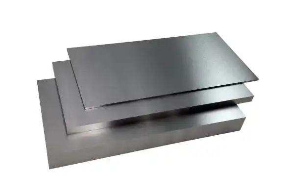
Molybdenum sits in a narrow class of refractory metals where the margin for error during welding approaches zero. Its melting point of 2623°C demands energy inputs that push conventional equipment to its limits, while its room-temperature brittleness means a weld that looks sound can crack during handling the next morning. I have seen shops lose entire production runs to cold cracking because they underestimated how quickly molybdenum’s ductile-to-brittle transition temperature (DBTT) shifts after thermal cycling. The metal does not forgive contamination, grain growth, or residual stress the way steel or aluminum might. What follows covers the material science behind these failures and the process controls that prevent them. Why Molybdenum’s Material Properties Dictate Every Welding Decision Molybdenum’s weldability is not a single variable but a cluster of interacting constraints. The 2623°C melting point means any arc or beam process must deliver concentrated energy without overheating adjacent material. Its low coefficient of thermal expansion reduces distortion during heating, yet the same property locks in residual stress during cooling because the material cannot relieve strain through contraction the way copper or aluminum does. The DBTT is the property that ends most molybdenum welding projects prematurely. Pure molybdenum transitions from ductile to brittle at temperatures above 20°C in many cases, so a weld that survives the cooling cycle can fracture at room temperature under minimal load. Recrystallization compounds the problem. Once the heat-affected zone exceeds roughly 1100°C, grain boundaries migrate and coarsen. Larger grains mean fewer boundaries to arrest crack propagation, and the weld becomes a liability rather than a joint. Material purity shifts these thresholds. Interstitial oxygen, nitrogen, and carbon raise the DBTT and lower the recrystallization temperature, narrowing the process window further. High-purity molybdenum plate, where interstitial content is controlled at the ingot stage, provides measurably better weld ductility than commercial-grade stock. The table below summarizes how each property influences process selection. Property Value Significance for Welding Melting point 2623°C Requires high energy density; limits filler metal options Coefficient of thermal expansion 4.8 × 10⁻⁶ /°C Low distortion but high residual stress accumulation Ductile-to-brittle transition temperature Typically above 20°C for pure Mo Room-temperature brittleness; cracking risk during handling Recrystallization temperature 1100–1200°C Grain growth above this range reduces ductility Thermal conductivity 138 W/m·K Rapid heat dissipation; demands concentrated heat input What Makes Molybdenum Welding Fail Five failure modes account for nearly every rejected molybdenum weld. Understanding their mechanisms is the first step
Calculating Tungsten Shielding: An HVL Guide
Radiation shielding calculations determine whether a design protects personnel or exposes them to unacceptable dose rates. For engineers specifying tungsten-based shields, the Half-Value Layer concept provides the quantitative foundation for thickness decisions. This article walks through HVL calculations for tungsten, compares performance against lead, and addresses the practical factors that influence shielding effectiveness in real installations. How the Half-Value Layer Defines Tungsten Shielding Performance The Half-Value Layer quantifies the material thickness required to reduce incident radiation intensity by exactly half. For tungsten, with its atomic number of 74 and density reaching 19.3 g/cm³, the HVL values are notably low compared to alternative shielding materials. This translates directly to thinner shield profiles for equivalent dose reduction. The relationship between HVL and the linear attenuation coefficient μ follows the formula HVL = ln(2)/μ, where ln(2) equals approximately 0.693. The coefficient μ represents the fraction of photons attenuated per unit thickness, and it varies with both material composition and photon energy. Tungsten’s electron density and atomic structure promote photoelectric absorption at lower energies and Compton scattering across the diagnostic and therapeutic energy ranges, making it effective across a broad spectrum. In a recent medical equipment project, substituting a high-density tungsten alloy for lead reduced shield volume by 35% while maintaining the required dose limits. The client needed a compact device footprint, and the density advantage of tungsten made that possible without compromising safety margins. This kind of outcome is typical when the application demands space efficiency. Material Density (g/cm³) HVL for 1 MeV Gamma Rays (cm) Lead 11.3 0.89 Tungsten 19.3 0.35 Steel 7.8 2.1 Concrete 2.3 6.0 Calculating Tungsten Shielding Thickness Step by Step Accurate shielding thickness calculations require systematic attention to source characteristics, regulatory limits, and material properties. The following sequence applies to most tungsten shielding designs: Specialized software handles complex geometries and multi-energy sources, but these fundamental steps underlie every shielding calculation. Skipping the buildup correction is a common error that leads to undersized shields in thick-barrier applications. What Factors Affect Tungsten Shielding Effectiveness Beyond HVL? The Half-Value Layer provides a starting point, but several additional factors determine whether a shield performs as designed in actual service. Radiation energy spectrum matters significantly. Higher-energy photons penetrate more deeply, requiring either greater thickness or materials with higher atomic numbers. A shield designed for 500 keV photons will underperform if the actual source includes a 1.5 MeV component. Source geometry influences effective shield
Tungsten Carbide Brazing: Filler Selection & Joint Design Mastery
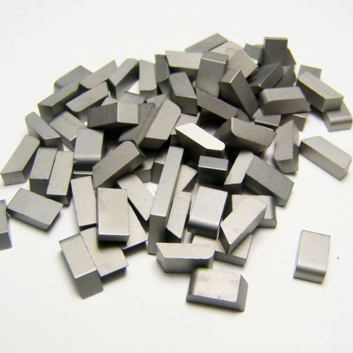
Tungsten carbide brazing sits at the intersection of metallurgy, thermal management, and mechanical design—and getting it wrong shows up fast. A joint that looks sound at room temperature can crack within hours under thermal cycling, or fail catastrophically when the tool hits its first hard workpiece. The difference between a reliable brazed carbide assembly and a warranty claim often comes down to decisions made before the torch ever lights: which filler metal, what joint geometry, how much gap, and how fast to cool. This piece walks through the technical framework behind those decisions. The focus is on practical methodology—what actually works when joining tungsten carbide to steel or other substrates, and why certain approaches fail. Engineers dealing with cutting tools, mining bits, or wear components will find the material directly applicable to specification and process development. Why Tungsten Carbide Creates Unique Brazing Challenges Tungsten carbide earns its reputation through a microstructure that combines hard WC grains with a metallic binder, usually cobalt. The cobalt content—anywhere from 3% to 30%—determines where a given grade falls on the hardness-toughness spectrum. A 6% cobalt grade like YG6 delivers hardness around 90.5 HRA but relatively modest transverse rupture strength. Push the cobalt up to 15% and you sacrifice some hardness for significantly better impact resistance, which matters in applications like heavy cutting or mining where shock loads are routine. The thermal expansion coefficient is where tungsten carbide becomes genuinely difficult to braze. At roughly 5-6 × 10⁻⁶/°C, carbide expands at less than half the rate of most steels. Heat a carbide tip brazed to a steel shank to 700°C, then cool it back down, and the steel contracts faster than the carbide. The result is residual tensile stress concentrated at the joint interface—exactly the loading condition that promotes cracking in brittle materials. Wettability compounds the problem. Pure tungsten carbide behaves more like a ceramic than a metal when molten filler tries to spread across its surface. Most conventional brazing alloys bead up rather than flow, leaving unbonded areas that become stress concentrators under load. Surface preparation or active filler metals become mandatory rather than optional. Carbide Grade Cobalt Content (%) Hardness (HRA) Transverse Rupture Strength (MPa) Typical Applications YG6 6 90.5 1500 Wear parts, cutting tools YG8 8 89.5 1800 Mining tools, dies YG15 15 87 2500 Impact parts, heavy cutting Different grades also respond differently to brazing temperatures. Higher cobalt content means more
Machining Pure Tungsten: Tools, Coolant, and Parameters
Pure tungsten sits in a category of its own among machinable metals. The combination of extreme hardness, brittleness at room temperature, and poor heat dissipation creates a narrow window for successful cutting operations. Most shops that attempt tungsten for the first time discover this the hard way—burned tools, cracked workpieces, and dimensional drift that defies their usual compensation methods. The material demands a complete rethink of cutting strategy. What works for steel, or even for other refractory metals like molybdenum, often fails spectacularly with pure tungsten. After three decades of working with this material, certain patterns emerge: the shops that succeed treat tungsten machining as a distinct discipline rather than an extension of their existing capabilities. Why Pure Tungsten Resists Conventional Machining Approaches Pure tungsten’s machinability problems stem from a specific combination of physical properties that interact in ways that amplify each other’s effects. The melting point of 3422°C sounds like it should make heat management easier, since the material won’t soften or deform under cutting temperatures. In practice, the opposite occurs. Tungsten’s relatively low thermal conductivity (173 W/m·K, compared to copper’s 400 W/m·K) means heat concentrates at the cutting zone rather than dissipating into the bulk material. The tool tip absorbs most of this thermal load, accelerating wear in ways that don’t follow the predictable patterns seen with steel. Brittleness compounds the thermal problem. At room temperature, pure tungsten has essentially no ductility. The material fractures rather than deforms, which means chips break unpredictably and cutting forces spike rather than flowing smoothly. A tool that’s slightly dull, or parameters that are marginally too aggressive, can initiate cracks that propagate through the workpiece. The density of 19.3 g/cm³ creates fixturing challenges that many shops underestimate. A tungsten blank weighs roughly 2.5 times what an equivalent steel piece would weigh, and the cutting forces required to remove material are correspondingly higher. Inadequate fixturing leads to vibration, which leads to chatter marks, which leads to stress concentrations, which leads to cracking. Property Pure Tungsten Steel (Typical) Melting Point 3422°C 1370-1538°C Density 19.3 g/cm³ 7.85 g/cm³ Hardness (HV) 350-400 150-250 Thermal Conductivity 173 W/m·K 45-50 W/m·K Modulus of Elasticity 411 GPa 200-210 GPa The high elastic modulus (411 GPa versus steel’s 200-210 GPa) means tungsten deflects less under load, which sounds beneficial until you realize it also means the material absorbs less energy through deformation. Forces that would cause a steel workpiece to
Tungsten Alloy Selection: An Engineer’s Practical Guide
Tungsten alloys occupy a strange position in materials engineering. They solve problems that most metals simply cannot handle, yet selecting the right one requires navigating a maze of compositional trade-offs that textbooks rarely explain clearly. After working through countless specification sheets and watching projects succeed or fail based on alloy choices, the patterns become clearer. The decision framework matters as much as the material data itself. What Makes Tungsten Alloys Different From Other Engineering Materials Tungsten alloys are composite materials that leverage tungsten’s unique attributes: high density, strength, and melting point. These properties make them indispensable in applications requiring extreme performance. The specific alloy composition significantly impacts mechanical properties and overall suitability for any given project. Three primary categories dominate the tungsten alloy landscape: Tungsten Heavy Alloys (WHA) contain 85-97% tungsten, typically bound with nickel-iron or nickel-copper. The binder phase allows for excellent machinability while maintaining the high density that makes these alloys effective for radiation shielding and counterweight applications. The tungsten particles remain suspended in a ductile matrix, which explains why these materials can be machined conventionally despite tungsten’s inherent brittleness. Tungsten-Copper Alloys (W-Cu) combine tungsten’s high melting point and arc resistance with copper’s excellent thermal and electrical conductivity. The two metals do not form a true alloy in the metallurgical sense. Instead, copper infiltrates a sintered tungsten skeleton, creating a composite where each phase contributes its dominant property. This makes them ideal for applications demanding both heat dissipation and electrical performance. Cemented Carbides (WC) represent the hardest end of the tungsten alloy spectrum. Tungsten carbide particles are sintered with a binder metal, usually cobalt, creating materials with extreme hardness and wear resistance. The carbide phase provides hardness while the binder contributes toughness, though the ratio between them determines whether the material excels at cutting or impact resistance. Alloy Type Primary Characteristics Typical Tungsten Content Key Applications Tungsten Heavy Alloy High density, machinable, radiation shielding 85-97% Counterweights, radiation shielding, kinetic energy Tungsten-Copper Alloy High thermal/electrical conductivity, arc resistance 10-50% Electrical contacts, heat sinks, EDM electrodes Cemented Carbide Extreme hardness, wear resistance, high compressive strength 70-97% Cutting tools, wear parts, dies Engineering Criteria That Actually Drive Tungsten Alloy Selection Selecting the correct tungsten alloy involves a systematic evaluation of critical engineering criteria. These factors determine an alloy’s suitability for specific operational environments and performance requirements. The challenge lies in prioritizing which properties matter most for your application, since optimizing one

Diamond Copper vs WCu Heat Sink: Thermal Performance Analysis
Managing heat in modern electronics keeps getting harder. Power densities climb, components shrink, and the margin for thermal error narrows with each generation. Two materials consistently surface in conversations about high-performance heat sinks: Diamond Copper composites and Tungsten Copper alloys. Both solve real problems, but they solve them differently. Having worked with these materials across various applications, the choice between them rarely comes down to a single number on a spec sheet. How Diamond Copper and Tungsten Copper Approach Heat Dissipation Diamond Copper takes an aggressive approach to thermal conductivity. The composite embeds diamond particles within a copper matrix, exploiting diamond’s rigid covalent lattice structure. Phonons travel through diamond with minimal scattering, which translates to heat moving fast. The copper component adds electrical conductivity and enough ductility to make the material workable, though “workable” is relative here. Tungsten Copper alloys follow a different logic. These powder-metallurgy composites blend tungsten’s density, strength, and high melting point with copper’s thermal and electrical properties. The ratio between tungsten and copper can be adjusted during manufacturing, which gives engineers a tuning knob for properties like thermal expansion and mechanical strength. Hubei Fotma produces Wcu Tungsten Copper Alloy with precisely controlled compositions, allowing thermal expansion coefficients to be matched to specific substrate materials. Material Density (g/cm³) Young’s Modulus (GPa) Diamond Copper 3.8 – 6.5 150 – 250 WCu (70W-30Cu) 14.5 320 WCu (80W-20Cu) 15.5 350 The density difference is substantial. Diamond Copper runs lighter, which matters in aerospace and portable applications. WCu’s higher density and stiffness make it structurally robust in assemblies that see mechanical stress alongside thermal loads. Raw Thermal Conductivity Numbers and What They Actually Mean Diamond Copper can exceed 600 W/mK in thermal conductivity. That number sounds impressive because it is. Diamond’s phonon transport mechanism moves heat with remarkable efficiency, and when those particles are distributed properly through a copper matrix, the composite inherits much of that capability. WCu alloys typically land between 170 and 220 W/mK, depending on tungsten content. Higher tungsten percentages reduce thermal conductivity but increase mechanical strength and lower the thermal expansion coefficient. The material research team at Hubei Fotma, drawing on over 30 years of technical experience, controls these tradeoffs through precise process parameters during sintering and infiltration. The gap between 600 W/mK and 200 W/mK looks decisive on paper. In practice, the relevance of that gap depends entirely on the thermal load and system constraints. A

Refractory Metals Properties Chart: W, Mo, Ta, Re, Nb, Ti, Zr
Working with metals that refuse to quit at extreme temperatures changes how you think about material limits. After years of specifying components for high-heat environments, the performance gap between refractory metals and conventional alloys becomes impossible to ignore. These materials hold their shape and strength where others would soften or fail entirely. What follows covers the essential characteristics and real-world uses of tungsten, molybdenum, tantalum, rhenium, niobium, titanium, and zirconium—the metals that make extreme engineering possible. What Makes Refractory Metals Different from Standard Alloys Refractory metals earn their classification through melting points that dwarf conventional metals. Tungsten tops the list at 3422°C, but even niobium at the lower end still melts above 2477°C. This thermal stability translates directly into maintained structural integrity and mechanical strength at temperatures exceeding 2000°C—conditions that would reduce most metals to puddles or at least severely compromise their load-bearing capacity. The property set extends beyond heat resistance. These metals typically combine exceptional hardness with wear resistance and chemical stability. That combination explains why they show up in applications where failure carries serious consequences. Aerospace relies on refractory metals for jet engine components and rocket nozzles where thermal cycling would destroy lesser materials. Defense applications demand their durability under extreme stress. Electronics manufacturing uses their electrical and thermal conductivity for advanced packaging and heating elements. Medical device makers value their biocompatibility and corrosion resistance. The common thread across these industries is an operating environment that pushes materials to their absolute limits. How W, Mo, Ta, Re, and Nb Compare on Critical Properties Selecting the right refractory metal requires understanding how their properties differ. The numbers tell the story more clearly than generalizations. Property Tungsten (W) Molybdenum (Mo) Tantalum (Ta) Rhenium (Re) Niobium (Nb) Melting Point (°C) 3422 2623 3017 3186 2477 Density (g/cm³) 19.25 10.28 16.69 21.04 8.57 Tensile Strength (MPa) 550-1900 400-1400 200-700 1000-1500 150-400 Hardness (HV) 350-450 150-200 60-120 220-270 40-70 Thermal Conductivity (W/m·K) 173 138 57 48 54 Tungsten dominates when maximum melting point and tensile strength matter. Its density of 19.25 g/cm³ makes it the heaviest option, which can be either an advantage or constraint depending on the application. Molybdenum offers a practical middle ground—high melting point, good thermal conductivity at 138 W/m·K, and roughly half the density of tungsten. Tantalum trades raw strength for ductility and corrosion resistance. Its tensile strength range of 200-700 MPa sits below tungsten and molybdenum, but its
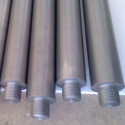
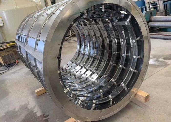
Molybdenum vs Graphite Heating Elements: Longevity and Performance
Choosing between molybdenum and graphite for industrial furnace heating elements comes down to understanding how each material behaves under real operating conditions. I’ve seen facilities make this decision based purely on temperature ratings, only to face unexpected maintenance cycles or premature element failure. The truth is, both materials perform exceptionally well in their respective sweet spots, but the wrong choice for your specific process can cost you significantly in downtime and replacement parts. How Molybdenum Performs as a Heating Element Molybdenum earns its place in high-temperature applications through a combination of metallurgical properties that few other materials can match. With a melting point of 2620°C, the metal maintains structural integrity at temperatures where most alternatives would soften or deform. What makes molybdenum particularly valuable is its creep resistance—the ability to hold its shape under sustained thermal stress without gradually sagging or warping over months of operation. The electrical characteristics work in your favor too. Molybdenum’s resistivity sits at 5.34 µΩ·cm at room temperature, which translates to efficient heat generation without excessive power draw. Mechanical strength at elevated temperatures exceeds what you’d get from most competing metals, giving heating elements the durability needed for continuous furnace operation. There’s a significant limitation to acknowledge. Molybdenum oxidizes aggressively above approximately 400°C when oxygen is present, forming volatile oxides that essentially cause the element to evaporate. This behavior restricts molybdenum heating elements to vacuum furnace applications or inert gas environments where oxygen levels stay strictly controlled. You’ll find these elements in sintering furnaces, brazing systems, and heat treatment equipment for ceramics and specialized alloys. FOTMA manufactures Molybdenum Rod and Molybdenum Plate Moly Sheet components for these applications, along with Customized Molybdenum Parts designed to fit specific furnace configurations. Property Value Melting Point 2620 °C Density 10.2 g/cm³ Thermal Conductivity 138 W/(m·K) at 20°C Electrical Resistivity 5.34 µΩ·cm at 20°C CTE (20-1000°C) 5.4 x 10⁻⁶ /K Modulus of Elasticity 329 GPa Oxidation Resistance Poor above 400°C Primary Atmosphere Use Vacuum, Inert Gas What Graphite Heating Elements Bring to the Table Graphite takes a different approach to high-temperature performance. The material doesn’t melt—it sublimes at temperatures exceeding 3600°C, which opens up operating ranges that molybdenum simply cannot reach. This characteristic makes graphite the default choice when processes demand temperatures above 2000°C. Thermal shock resistance sets graphite apart in applications with rapid heating and cooling cycles. The crystalline structure absorbs thermal stresses that would crack or fracture